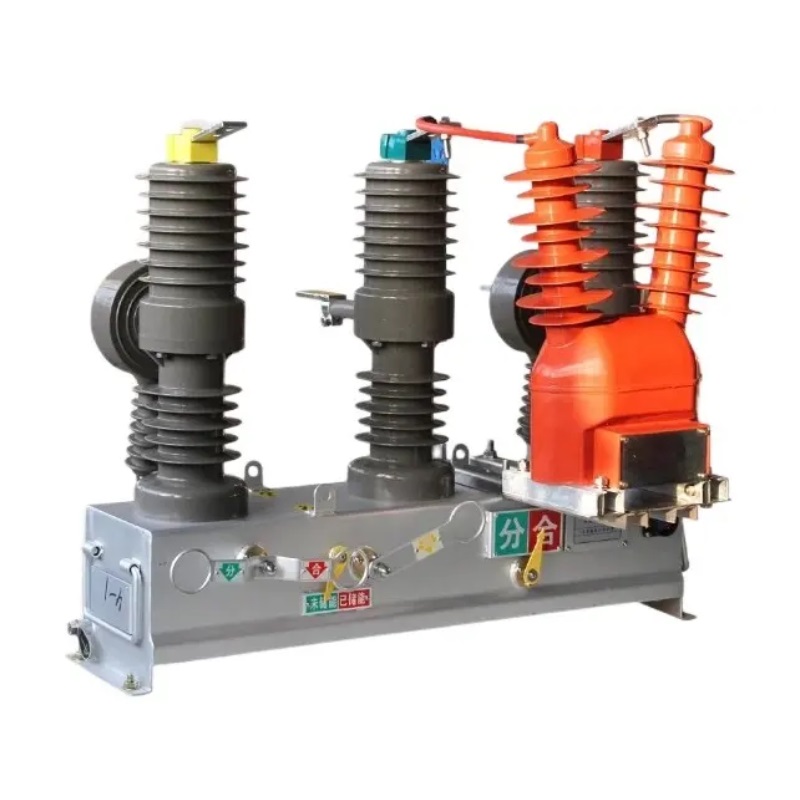
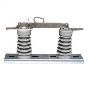
ZW32-12F Outdoor vacuum circuit breaker
Overview
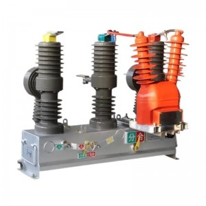
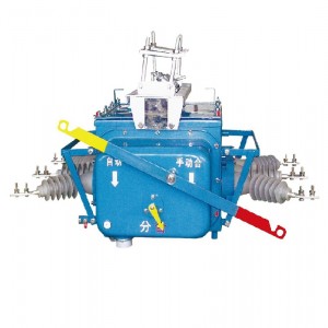
ZW32-12F disconnector is an outdoor power distribution equipment with rated voltage 12KV induction AC 50Hz. It is mainly used to open and close the load current, overload current and short-circuit current in the power system.
The main purpose is to open and close the load current, overload current and short-circuit current in the power system. It is suitable for protection and control in power distribution systems of substations and industrial and mining enterprises, and more suitable for rural power networks and places of frequent operation.
The product can meet the requirements of the automatic system and perform the traditional Recloser function reliably and effectively. The switch uses vacuum interrupter as the interrupting medium.
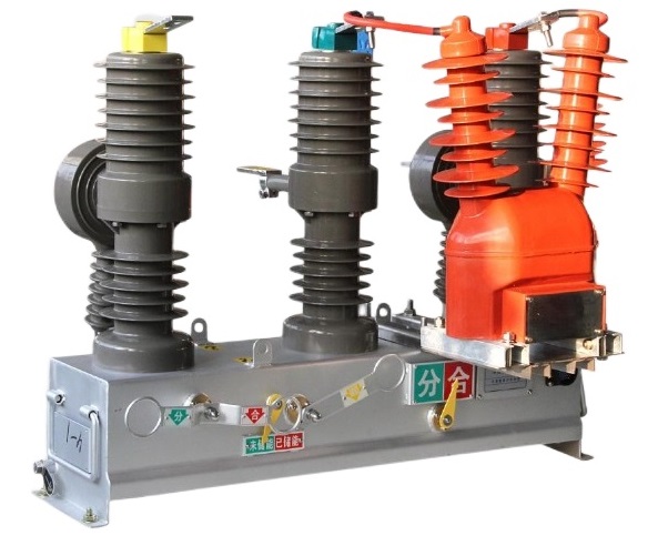
★ Vacuum arc extinguishing, stable opening and closing performance
★ Three-phase pillar type structure
★ Built-in miniaturized spring mechanism, low energy consumption for breaking and closing
★ Equipped with two-phase or three-phase core-penetrating transformer
★ Small volume, light weight, low maintenance, long life
★ Outdoor epoxy resin or silicone rubber casing, high and low temperature resistance, UV resistance, aging resistance
★ The current transformer is made of high-quality magnetic conductive material and epoxy resin with silicone rubber load, insulation, which has the advantages of large capacity, high dynamic and thermal stability multiplier, high precision grade, maintenance-free operation, and high reliability.
★ Can be matched with controller to realize distribution automation
Environmental conditions of use
2. Ambient air temperature: -40℃~+40℃;Daily temperature difference: daily temperature change 25 ℃;
3. The wind speed is not greater than 35 my/s;
4. No flammable, explosive hazard, strong chemical corrosion (such as various acids, alkalis or dense smoke, etc.) and places with severe vibration.
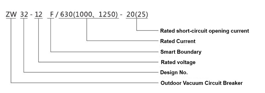
Model number and meaning
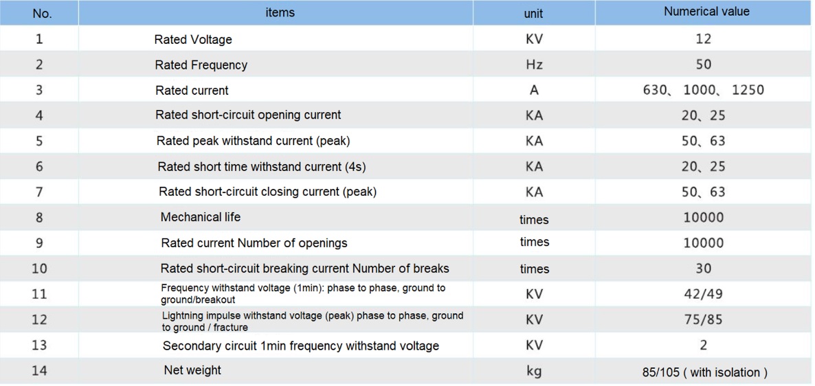
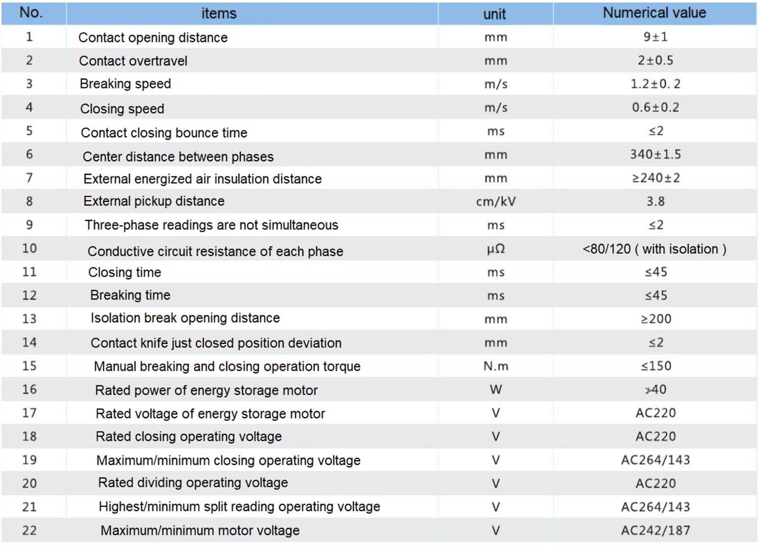
Main technical parameters(Table - 1)
The product is operated from a low-voltage AC/DC220V (110V) power source supplied by the user or from a secondary voltage AC220V (110V) directly connected to a voltage mutual inductor (external) from an overhead line.
The source. Built-in protection, zero-sequence current mutual inductor, three, the ratio of 600/1.
Operating mechanism
This product is electric energy storage, electric opening and closing, and also has manual energy storage, manual opening and closing, over-current protection, the whole structure consists of closing spring, energy storage system, over-current release, opening and closing coil, manual opening and closing Reading system, auxiliary switch and energy storage indication and other components.
Action Principle
Energy storage process.
Pull the mechanism manual energy storage pull ring, or give the mechanism, electric energy storage signal, the motor drives the energy storage arm to store energy to the energy storage spring, and maintain this energy through the energy storage holding loop.
Closing process.
When closing the circuit breaker, pulling the manual closing ring or giving the electric closing signal to the machine, the closing spring energy is released, the output shaft of the machine rotates, and the moving contact of the interrupter is moved upward through the inflection arm and the driving linkage plate to contact the static contact and provide contact pressure, while storing energy for the breaking spring and keeping the circuit breaker in the closed state through the normal buckling of the closing holding loop of the machine.
Breaking process.
When the circuit breaker is broken, the manual breakout ring of the mechanism is pulled or the electric breakout signal is given to the mechanism, and the closing retaining ring of the mechanism is unlocked. The breaking state is maintained by the switch breaking spring.
Overcurrent protection process.
When the current flowing through the main circuit of the interrupter exceeds the rating of the interrupter, the current output from the secondary side of the interrupter will signal the controller, and the controller will give the operating voltage to the breaking coil, causing the interrupter to break.
Connection between controller and switch
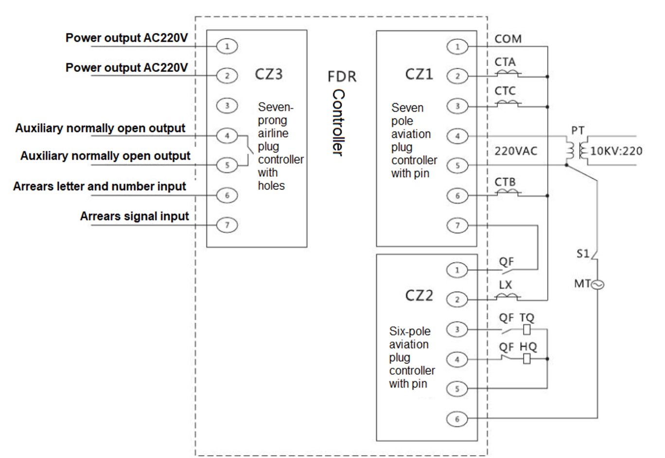
BKM600-FDR Controller Wiring Diagram
Description:
CTA is A-phase CT; CTB is B-phase CT; CTC is C-phase CT; LX is zero-sequence CT.
TQ is the breaking coil; HQ is the closing coil; Q is the breaker auxiliary switch.
MT is the energy storage motor; S is an energy storage, auxiliary switch; PT is a voltage mutual inductor
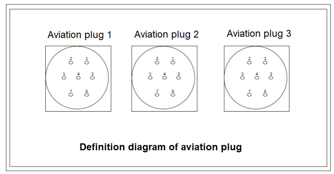
Aviation plug connection
Dial code operation
Select the band according to the dial table, and the corresponding value is the fixed value and time limit required by the user. The list is as follows: 5S.
Aviation plug pin definition table
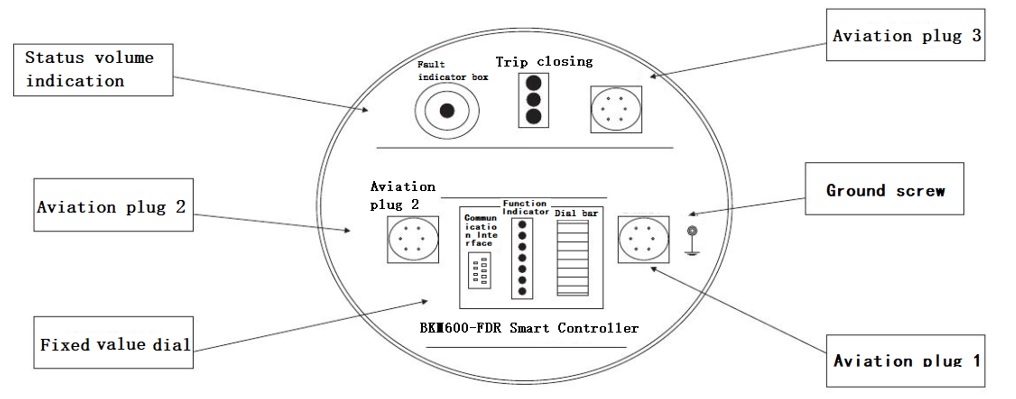
After the BKM600-FDR controller is installed on the pole, please connect the aviation plug according to the marked position on the panel, tighten the grounding bolt and ensure reliable grounding.
Refer to the Plug Plug Pin 1 and 2 Definitions table for wiring definitions.
Schematic diagram of BKM600-FDR device panel
Instructions for color high-brightness LED lights
Note: The working status of the controller can be determined by observing the various color indicators on and off at the bottom of the controller, and the SOE event log can be accessed through the LCD panel.
Control power supply and opening and closing control voltage
The power supply the BKM600-FDR controller comes from the high-voltage transformer, the rated voltage of the power supply is AC220V, 50HZ, after the aviation plug of the power supply is connected, the controller automatically enters the working state, and the controller has a built-in 2A-6A fuse.
On-column switch The energy storage motor is powered by PT voltage, which is connected to the on-column switch after passing through the controller.
The BKM600-FDR controller has its own internal energy storage capacitor, and the opening and closing energy come from this capacitor. In order to avoid the influence of line voltage fluctuations on the opening and closing operation, the opening and closing control circuit output voltage of the circuit is DC220V DC voltage. When the circuit voltage drops suddenly, the capacitor can provide a time not less than 8S to maintain the work of the BKM600-FDR controller and release once.
Note: The BKM600-FDR controller adopts a voltage-stabilizing charging method to ensure that the energy storage capacitor is around DC220V, and the charging time of the capacitor is less than 0.5S.


Products categories
- Online


